The Outward Overland Trailer: Electrical System Design & Diagram
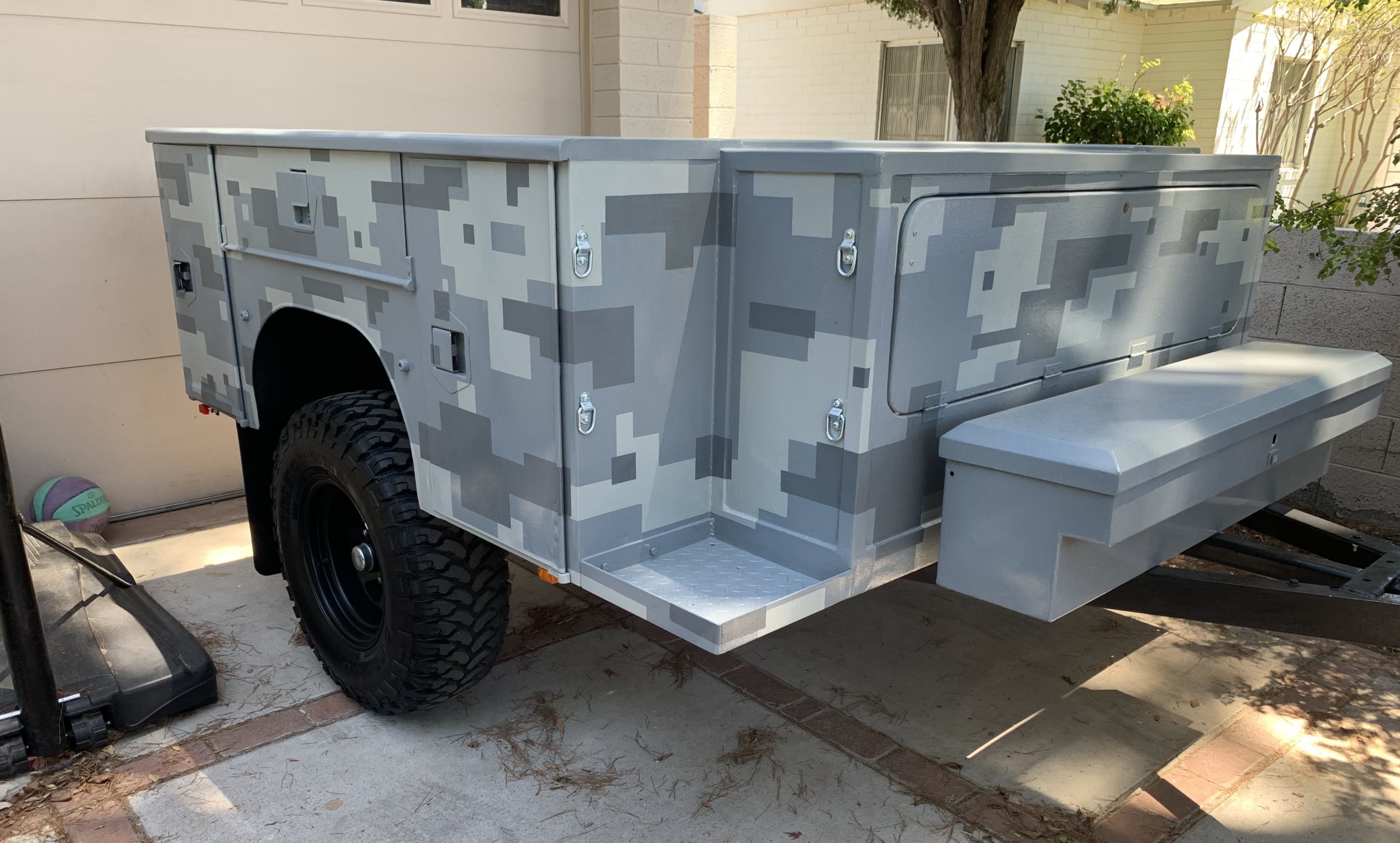
We purchased a custom off-road trailer to use as a platform to build the perfect overland trailer. We’ve spent the past few years adding an electrical system, a water system, a pull-out kitchen, and a roof rack system to complete the build. In this post, we’ll share the design decisions and wiring diagram of our overland trailer electrical system. To learn more about our overland trailer build, visit the first post in our Outward Overland trailer Series.
Getting Started
We started by calculating our power needs by conducting an energy audit based on our projected electrical needs. To conduct an energy audit, you determine the power draw (in amps) of each electric component in your system and multiply the amount of power of each device by the time per day (in hours) you plan to use it. This gives you a list of projected amp hours (Ah) you’ll use each device per day. Add them together and you have your projected daily Ah usage.
Our list of desired electrical systems included a pressurized water system with hot water, a 12v refrigerator, and lighting throughout the various trailer compartments. Conducting our energy audit on our planned usage, we determined we would use about 20 amp hours of power per day. Our experiences with an airstream trailer in the past confirmed that 20Ah per day was a good target to shoot for.
Planning our 12V Electrical System
Once we had our target daily usage of 20Ah, we could then begin to size our power storage and recharging systems. We determined that an average trip using our overland trailer would be about 3 days – mostly long weekends. 3 days of 20Ah of power usage meant that we needed at least 60Ah of battery storage. When it comes to batteries, more is always better providing the budget and space allow. With that in mind, we upped our desired battery bank size to 100Ah – giving us the potential to spend 5 days out in the wild without needing to recharge.
In terms of recharging our batteries, we first needed a way to recharge them when we returned home to the power grid. We landed on a 10-amp 120V battery charger for recharging the batteries at home. We also wanted the ability to recharge the batteries with solar panels. We calculated that adding around 200 watts of solar would give us between 20Ah to 50Ah of charging capability per day, depending on conditions.
With these numbers, we began purchasing the best components to fit our build.
Main Electrical System Components
Batteries
Batteries are typically the single largest purchase in your electrical system. On a budget, we purchased two 6V 210Ah “golf cart” batteries from Costco. Needing to get these 6V batteries to output 12V, we wired them in series to double the voltage to 12V and keep the amp hours at 210Ah. These golf cart batteries are traditional wet cell deep cycle batteries (not AGM or Lithium Ion) which shouldn’t be discharged to less than 50% of capacity to maintain the health of the battery. So 210Ah at 50% depth of discharge would give us 105Ah of usable power.
To fit the batteries into the front “electrical” compartment in our trailer, we fabricated a battery box out of angle iron and installed tie-down straps to keep them in place.
Battery Monitor
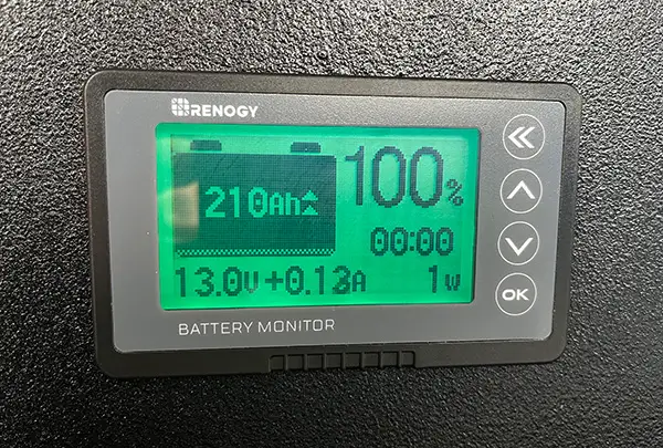
To manage our electrical system and to closely monitor our battery capacity while on adventures, it was important for us to install a good battery monitor. We choose Renogy’s 500A Battery Charger with Shunt. It’s inexpensive, monitors power going both in and out of your batteries, and keeps track of your net usage compared to your battery capacity.
To monitor your system’s power usage, the Renogy battery monitor uses a shunt which wires as the first component on the negative side of your battery. To ensure you measure ALL power usage, all charging and discharging devices must be wired behind this shunt.
The shunt then connects to the monitor display via a thin communication cable, which we installed later in the build.
Read our full review of the Renogy 500A Battery Monitor
Battery Disconnect Switch
To have control to shut down our electrical system to work on it or when the trailer is stored for long periods of time, we installed a battery disconnect switch in our system.
Like the battery monitor shunt, the disconnect switch must be wired early in the circuit with all other devices wired behind to ensure all devices can be disconnected from the battery. As you can see on our wiring diagram below, we wired our disconnect switch on the positive side of the battery.
250A System Fuse
Between the battery and the disconnect switch, we added a 250A system fuse on the positive battery terminal. In an event of a short circuit or component malfunction, this fuse will blow protecting the rest of our system. We sized this quite large to allow normal operation to occur without incident.
Bus Bars
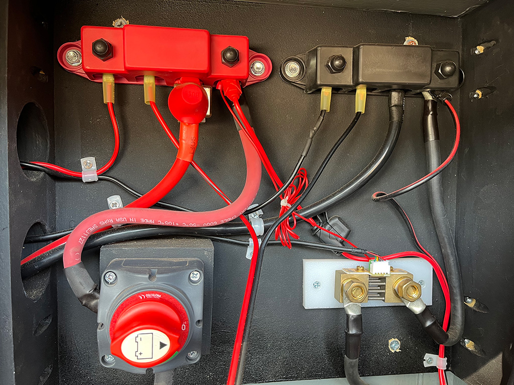
Bus Bars, or power distribution blocks, aren’t always necessary but are a convenient way to keep your electrical system installation clean and organized. Bus bars provide multiple mounting posts for components to be wired together and make the installation of larger wires much simpler.
The biggest reason we choose to use both positive and negative bus bars in our build was to create single sources of contact to our disconnect switch on the positive side and our shunt on the negative side. The bus bars allowed to easily wire all other components behind the disconnect and shunt with a single wire between them and the busbar.
Shore Power Charging Components
120V Battery Charging
The term “shore power” comes from the marine industry, referring to a boat or ship being able to plug into the power grid when in port. For camping trailers or RVs, shore power is a 120V power source used for system charging when a connection to the power grid is possible.
For our shore power system, we chose NOCO’s Genius 10 – a simple 10A 120V car battery charger. We installed the NOCO charger into our electrical compartment and wired both positive and negative wires to their respective bus bars.
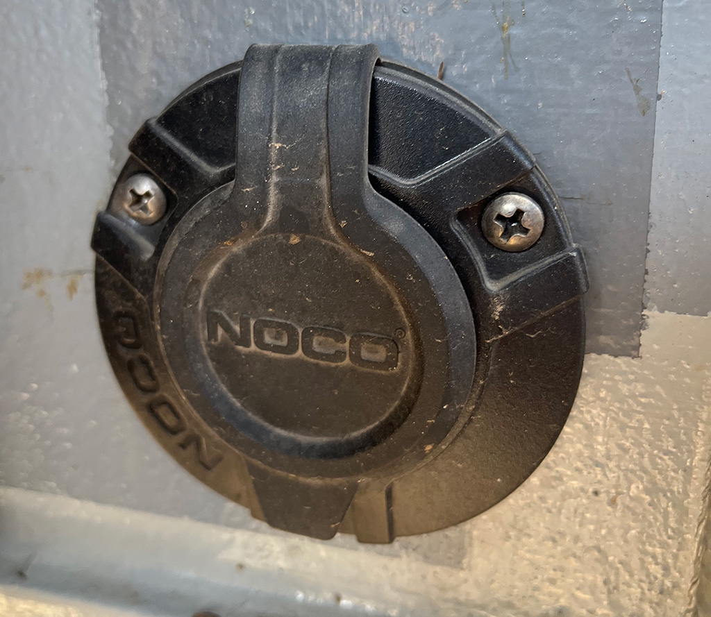
Plugging In
Because we installed the shore charger inside our electrical compartment, we needed a way to easily plug in a 120V power cord to charge the system. We installed NOCO’s waterproof 120V plug into the exterior of our electrical compartment and plugged the interior side into the charger. With this setup, we can plug in using a household extension cord in seconds.
With various and automatic charging phases, we can leave the NOCO battery charger plugged in for long periods of time without concern of overcharging or damaging our batteries
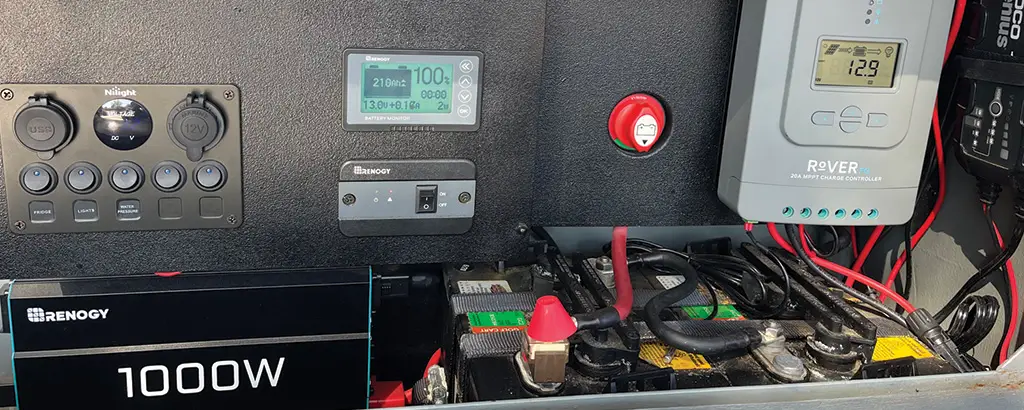
System Display/Control Components
12V Switch Panel
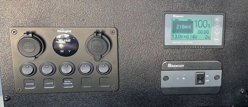
To add 12V circuits to separate and protect our various electrical components, we installed a Nilight 5-switch panel with 2 USB charging ports and a 12V “cigarette lighter” port. Protected with a 15A fuse, this panel also includes a voltmeter to verify our system voltage with the Renogy battery monitor.
To wire the panel into the system, we wired its source wires to the busbars, cut a hole into our control panel box and attached the panel via the corner screws.
We currently only use 3 of the switches, leaving 2 additional switches to expand our electrical components in the future. We have switches for our trailer’s led lighting, 12V water pump, and 12V refrigerator. Each of these components can be switched on and off as we need them. Being able to turn individual systems helps to reduce parasitic power waste in each of these systems when they are not in use.
The USB ports also come in handy for charging phones and other small devices while we are at the campsite. We use the 12V “cigarette lighter” port for our air compressor when needed.
Battery Monitor Display
We have the display for our Renogy Battery Monitor installed next to our switch panel and inverter switch in the middle of our electronics compartment. The battery monitor has a large display with adjustable backlighting, allowing easy viewing without having to turn on the lights.
We love that the battery monitor display shows us the net power usage in real-time. It also displays our current battery capacity in both percentage and icon. With the data, we can monitor our power usage closely ensuring we have enough power for the duration of our trip.
Inverter On/Off Switch
Our 1000w inverter has a separate switch installed in our control panel. While this switch we can quickly switch the inverter on when we need it and off when we don’t. Being able to turn the inverter off when we don’t need it avoids a small amount of parasitic power draw that it pulls when switched on. The switch also includes a power led as well as an error led to indicate problems with our inverter.
120V AC Components
1000W Pure Sine Wave Inverter
When designing our overland trailer electrical system, we chose to add a power inverter to the system. Inverters convert 12V DC power from the batteries to 120V AC power to use with most household devices. Pure sine wave inverters create clean and safe power that can be used for sensitive electronics like computers.
For our trailer, we purchased Renogy’s 1000W Pure Sine Wave Inverter. 1000W gives us enough wattage to use most electronics, but not quite enough to run high-power electronics such as hair dryers, electric kettles, or most heaters. These types of devices use a lot of power and with our desired 20A/day budget, we decided that we didn’t even want the temptation on this trailer. Besides, we planned a propane system on our trailer for cooking and heating.

125A Inverter Fuse
To install our inverter, we wired the inverter’s DC inputs into both busbars and added a 125A fuse inline for added protection. We then ran the small communication cable to the on/off switch on the control panel.
Getting 120V power out
Our inverter has two 120V AC outlets built into its side. Since the inverter is mounted inside our electrical compartment, we installed a waterproof AC outlet to the exterior of our trailer and plugged it into one of the inverter outlets.
Once the inverter is switched on, we can simply plug our AC devices into this plug on the outside of our trailer to get power. The inverter’s second outlet allows us to plug in additional devices to utilize the inverter’s power as needed.
Solar System Components
Solar Panels
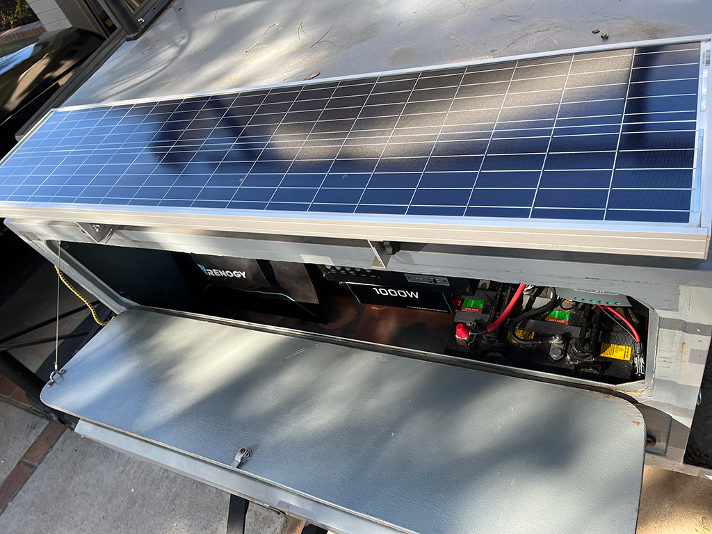
To recharge our batteries while we’re away from the grid, we looked for the best way to add around 200w of solar panels to our trailer. While the top of our trailer is large and flat, we avoided placing panels on the trailer “lid” due to extra weight and the shadows that our roof rack accessories would cast on the panels. The best placement for a rigid was on the top of our electrical compartment at the front of our trailer. But being only 13 inches deep, typically sized 100w rigid solar panels wouldn’t fit. After a long search, we found an 80w slim rigid solar panel from NAZ Solar Electric.
We installed the 80w slim solar panel using an adjustable mounting system which allows us to adjust the angle of the panel to catch the most amount of sunlight. The cables pass through the roof of our electric compartment using a solar gland to keep water out.
As we didn’t have room to permanently mount all of our solar panels on the roof of our trailer, we purchased a 100w foldable solar suitcase from Renogy to add to our system. This portable solar panel gives us the flexibility of adding more power when we need it and allows us to move and point the 100w panel throughout the day to produce more power.
Now with 180w of solar panels, we purchased a solar parallel adapter cable giving us the ability to connect both panels in parallel with one output to the charge controller. We wired the rigid 80W panel to one end of this cable and connected the other end to a waterproof SAE-style solar input socket mounted to the side of the trailer. The solar input plug adds an easy way to plug in the solar cables from our 100w portable panel when needed.
Solar Charge Controller
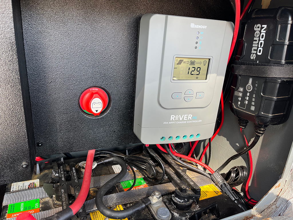
To control the battery charging ability of our solar generation, we chose Renogy’s Rover 20A MPPT Solar Charge Controller. The MPPT controller converts the higher voltage from the parallel wiring of our panels to the best voltage to charge our batteries.
The charge controller is wired to the battery via the positive and negative busbars and also provides multi-phase charging to protect our batteries. We’ve added Renogy’s optional BT-1 Bluetooth adapter which provides the ability to monitor the status of your solar system via a smartphone.
Our controller is mounted just above our batteries in our electrical compartment, which is convenient for the placement of the included battery temperature sensor.
Summary
While we’ll surely add and expand our trailer’s electrical system in the future, planning our system by starting with an energy audit ensured we started on the right track. Our electrical system allows us to spend 5 days in the wild and more if the sun is readily available. It powers our lighting, water system, refrigeration, and device charging while camping without trouble. And when we return, it can be recharged easily and quickly from the grid.
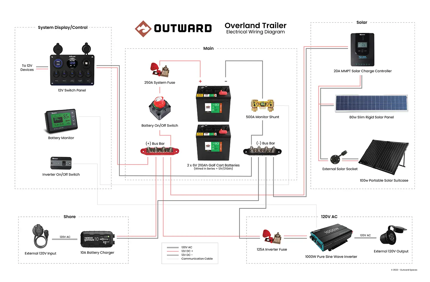
If you are interested in diving deeper into the specific components we used on our build or would like to use our build as inspiration for your own RV, van, or trailer electrical system build, please view our interactive wiring diagram below. You can also download the diagram in pdf format which also includes clickable links for each component.
Interactive Wiring Diagram
Hover/Click on The Components for More Info


Leave a Reply